Paired FG-3+ Sensors
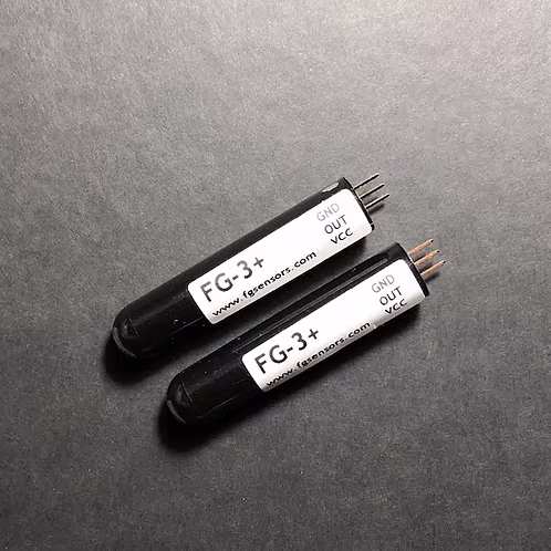
Paired FG-3+ Sensors are two matched FG-3+ 1-axis fluxgate magnetometers selected for use together in gradiometer systems.
Matching sensors improves measurement symmetry and reduces offset errors between sensors, which is important when measuring magnetic field gradients.
These sensor pairs are commonly used in:
- gradiometers
- differential magnetometers
- metal detection systems
- geophysical instruments
What Is a Sensor Pair?
A paired sensor set consists of two FG-3+ sensors with closely matched electrical and magnetic characteristics.
Using matched sensors helps ensure:
- similar sensitivity
- similar output frequency characteristics
- stable differential measurements
This improves the performance of magnetic gradient measurements.
Gradiometer Principle
A gradiometer measures the difference between two magnetic field measurements separated by a fixed distance.
Instead of measuring the absolute magnetic field, the system measures the gradient between two sensor positions.
This technique suppresses background geomagnetic variations and highlights local magnetic anomalies.
Advantages:
- reduced environmental magnetic noise
- improved detection of buried ferromagnetic objects
- higher sensitivity to local magnetic disturbances
Sensor Characteristics
Each sensor in the pair has the same specifications as the standard FG-3+ fluxgate magnetometer.
| Parameter | Value |
|---|---|
| Sensor Type | 1-Axis Fluxgate Magnetometer |
| Magnetic Range | ±50 µT |
| Supply Voltage | 5 V |
| Typical Current | ~12 mA |
| Output Type | Frequency / square wave |
| Output Frequency Range | ~50 kHz – 120 kHz |
| Bandwidth | DC – 20 kHz |
The sensor outputs a 5 V rectangular pulse signal whose period is proportional to the magnetic field strength along the sensor axis.
Output Signal
Each FG-3+ sensor outputs a frequency signal proportional to the magnetic field.
Typical output characteristics:
| Magnetic Field | Frequency |
|---|---|
| +50 µT | ~120 kHz |
| −50 µT | ~50 kHz |
Equivalent signal period range:
| Period |
|---|
| ~8.5 µs – 25 µs |
The magnetic field value can be calculated by measuring the frequency or period of the output signal.
Typical Gradiometer Configuration
A basic gradiometer using paired sensors includes:
- 2 × FG-3+ sensors
- signal processing electronics
- data logger or microcontroller
- mechanical mounting structure
Sensor spacing is selected based on the application and required sensitivity.
Typical Applications
Geophysical Surveys
- underground structure detection
- geological exploration
- buried pipeline detection
Metal Detection
- deep ferromagnetic object detection
- treasure hunting instruments
- UXO detection
Archaeology
- buried artifact detection
- site mapping
- archaeological surveys
Space Weather and Geomagnetic Monitoring
- aurora monitoring stations
- geomagnetic observatories
- magnetic disturbance detection
Integration
Paired FG-3+ sensors can be used with:
- Converter Circuit Board
- MAG-BOARD
- DIY Gradiometer Kit
- FGA Logger systems
- custom microcontroller electronics
Most systems measure the frequency output of each sensor independently and calculate the magnetic gradient digitally.
Related Products
- FG-3+ Sensor — single 1-axis fluxgate sensor
- Converter Circuit Board — frequency-to-voltage interface board
- MAG-BOARD — magnetometer signal processing board
- DIY Gradiometer Kit — complete gradiometer system using paired sensors