Assembling the MAG-BOARD
The MAG-BOARD is the main electronics module of the DIY Gradiometer Kit. It processes signals from the FG-3+ sensors and controls the display, buttons, and audio feedback.
Most components are already pre-soldered on the board. However, several external parts must still be connected before the system can be used.
If you purchased a fully assembled MAG-BOARD, this step may already be completed and you can skip this section.
Components to Install
The following components typically need to be connected to the MAG-BOARD:
- power cable
- sensor connectors
- buzzer
- optional buttons
- optional LED indicators
These components provide power, sensor connectivity, and user interface functions.
Power Cable Installation
The MAG-BOARD is powered using a two-wire power cable.
Correct polarity is extremely important. Connecting the wires incorrectly may damage the electronics.
| Wire | Terminal |
|---|---|
| Black | Negative (−) |
| Red | Positive (+) |
Ensure the wires are soldered firmly and routed so they do not interfere with other components.
Sensor Connections
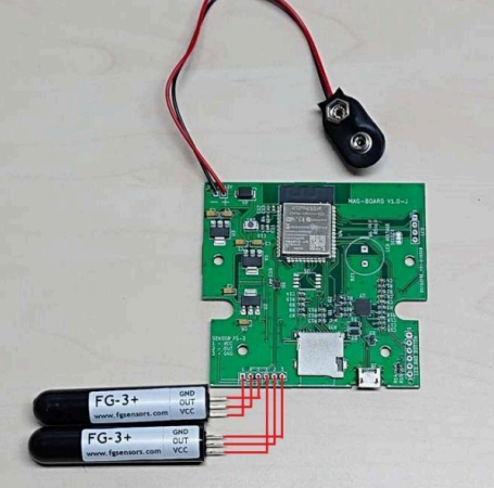
Two FG-3+ sensors connect to the MAG-BOARD.
Each sensor must be connected to the appropriate connector on the board:
Upper sensor → upper connector
Lower sensor → lower connector
Make sure the cables are routed correctly and secured to prevent movement during operation.
Incorrect wiring or loose connections may cause unstable measurements.
Buzzer Installation
The buzzer provides audio feedback during operation.
Typical uses include:
- signal indication
- threshold alerts
- system feedback
The buzzer must be soldered to the designated pads on the MAG-BOARD. Ensure correct orientation according to the board markings.
Optional User Interface Components
The MAG-BOARD allows installation of additional controls.
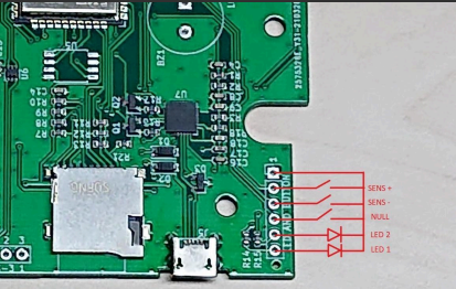
Up to three buttons and two LEDs can be connected.
| Component | Function |
|---|---|
| NULL Button | Calibration / zeroing |
| "+" Button | Increase sensitivity |
| "−" Button | Decrease sensitivity |
| LED 1 | System status |
| LED 2 | Signal indicator |
These controls allow users to adjust the gradiometer during operation.
LCD Voltage Selection
If using the LCD display supplied with the MAG-BOARD, no configuration changes are required.
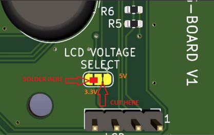
However, if using a 3.3 V LCD display, the voltage selection jumper must be modified:
- Locate the LCD voltage selection jumper on the board
- Cut the default connection
- Bridge the 3.3 V side with solder
This ensures the LCD operates at the correct voltage level.
Optional External Flash Memory
The MAG-BOARD includes support for external flash storage.
Users can install an SPI flash memory chip to store measurement data.
Recommended chip: W25Q32JVSS
Other compatible SPI flash devices may also be used. The memory chip must be soldered to the designated pads on the board.
Final Checks
Before continuing to the next step, verify the following:
- power cable polarity is correct
- sensor connectors are securely attached
- buzzer is installed correctly
- optional buttons and LEDs are properly connected
- LCD voltage configuration matches the display type
Once the electronics are assembled, continue with: