Sensor Wiring
This page covers the electrical interface of the FG-3+, FG-3C, and FG-4 sensors — including output types, supply requirements, and wiring recommendations.
Sensor Comparison
| Sensor | Axes | Output Type | Supply Voltage | Typical Integration |
|---|---|---|---|---|
| FG-3+ | 1 | 5 V PWM | 5 V regulated | Frequency counting on MCU or Converter Board → ADC |
| FG-3C | 1 | UART / Analog / PWM (selectable) | 5 V regulated | UART RX on MCU, analog input, or DAQ |
| FG-4 | 3 | 5 V PWM per axis | 5 V regulated | Frequency counting (3 channels) on MCU |
FG-3+
The FG-3+ outputs a 5 V PWM whose period is proportional to the magnetic field strength along the sensor axis. Higher field strength along the sensitive axis results in a shorter pulse period.
Wiring
The FG-3+ connects via a 3-wire interface:
| Connection | Description |
|---|---|
| VCC | 5 V regulated power supply |
| GND | Signal and power ground |
| OUT | 5 V pulse output — connect to MCU timer/counter input |
Exact connector pin numbering is not documented publicly. Refer to the label or silkscreen on your specific sensor unit for VCC / GND / OUT identification.
Practical Notes
- Frequency counting: The MCU must measure the period of the incoming pulse using a timer in input-capture mode, or by counting transitions. Do not use simple
digitalRead()polling for accurate results. - Level shifting: The output is 5 V logic. If your MCU operates at 3.3 V (e.g., ESP32, Arduino Due), use a resistive voltage divider or a dedicated level shifter on the OUT line.
- Cable length: For longer cable runs, use shielded cable to reduce picked-up interference. Connect the shield to GND at one end only.
- Power decoupling: Place a 100 nF ceramic capacitor close to the sensor VCC pin to suppress supply noise.
FG-3C
The FG-3C is a 1-axis fluxgate magnetometer with a configurable output mode. The output mode is selected by the pin configuration at startup.
Output Modes
| Mode | Output | Notes |
|---|---|---|
| UART | Digital serial text at 115200 baud | Field value in nT as ASCII text |
| Analog | Voltage proportional to field | Suitable for ADC or oscilloscope |
| PWM | PWM duty cycle proportional to field | Suitable for simple MCU capture |
Documented Pinout
| Pin | Function |
|---|---|
| 1 | VCC (5 V regulated) |
| 2 | GND |
| 3 | Mode select / Analog output |
| 4 | UART TX (in UART mode) / PWM output |
| 5 | Mode select |
Pin functions for non-UART modes are not fully documented publicly. Refer to the FG-3C datasheet or contact FG Sensors for the complete configuration table.
UART Mode Wiring
Connect Pin 4 (UART TX) of the FG-3C to the RX pin of your MCU or USB-UART bridge.
FG-3C Pin 4 (TX) ──────► MCU RX
FG-3C Pin 1 (VCC) ─────► 5 V
FG-3C Pin 2 (GND) ─────► GND
- Baud rate: 115200
- Data: 8N1
- Output: ASCII text, field value in nT
Pin 4 is a 5 V UART signal. Connect to a 3.3 V MCU only through a level shifter or voltage divider.
FG-4
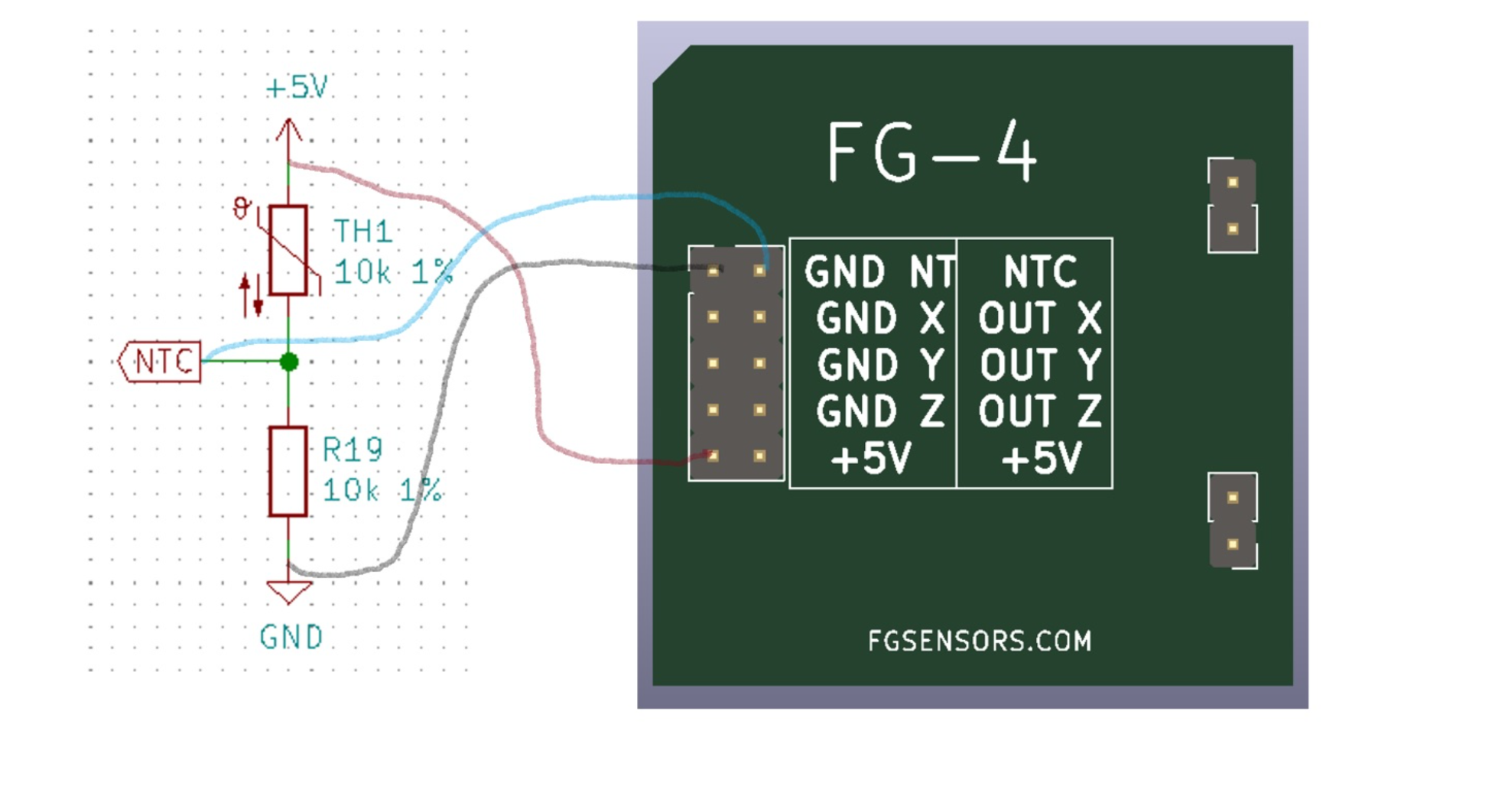
The FG-4 is a 3-axis fluxgate magnetometer that provides three independent frequency-output channels — one per axis (X, Y, Z) — plus an NTC thermistor output for temperature compensation.
Connector Pinout
The FG-4 uses a 10-pin connector with two columns:
| Left pin | Right pin |
|---|---|
| GND NTC | NTC |
| GND X | OUT X |
| GND Y | OUT Y |
| GND Z | OUT Z |
| +5V | +5V |
Axis Enable — GND-Switched Design
The +5 V supply powers all axes from a shared supply rail. To enable a specific axis, you must connect GND to that axis's GND pin:
- Read X only → connect GND to GND X
- Read all three axes → connect GND to GND X, GND Y, and GND Z
The three axes can interfere with each other when active simultaneously. For the highest measurement quality, read one axis at a time. Reading all three axes simultaneously is possible if required by your application.
NTC Temperature Output
The NTC thermistor output uses a voltage divider formed by TH1 (10 kΩ 1%) in series with R19 (10 kΩ 1%) between +5 V and GND.
| Condition | NTC Output Voltage |
|---|---|
| 25 °C | ~2.5 V |
| Below 25 °C | Decreases |
| Above 25 °C | Increases |
Connect the NTC pin to an ADC input on your MCU to read temperature. Connect GND NTC to signal ground.
Schmitt Trigger / Level Shifting
A Schmitt trigger on the OUT lines is not strictly required, but is recommended for clean digital edges — especially over longer cable runs. On the MAG-BOARD, the Schmitt trigger also acts as a level converter, translating the 5 V PWM output from the FG-4 down to the 3.3 V logic level required by the ESP32.
If you are integrating the FG-4 directly into a 3.3 V system without the MAG-BOARD, add a level shifter or resistive voltage divider on each OUT line.
Practical Notes
- Three independent timer/counter channels are required on the MCU — one per axis
- All three outputs are 5 V logic; apply level shifting for 3.3 V systems
- The three axes are orthogonal and factory-aligned — do not rotate the sensor body relative to the measurement frame
- Power supply must be clean and regulated; all three axes share a common +5 V supply
General Wiring Best Practices
- Always use a regulated 5 V supply — sensor accuracy is affected by supply noise
- Keep sensor wiring away from high-current traces or switching regulators
- For multi-sensor systems (gradiometers), use separate shielded cables for each sensor and ensure a common GND reference
- Label all sensor cables at both ends to avoid axis confusion in multi-axis or multi-sensor setups