Calibration
Calibration aligns the upper and lower FG-3+ sensors so that the gradiometer correctly measures the magnetic field gradient.
This process ensures that both sensors respond consistently when the instrument is rotated, which is essential for accurate detection of magnetic anomalies.
Calibration is one of the most important steps in assembling the gradiometer.
Required Tools
- a plastic or non-metallic screwdriver
- a non-metallic V-block bracket
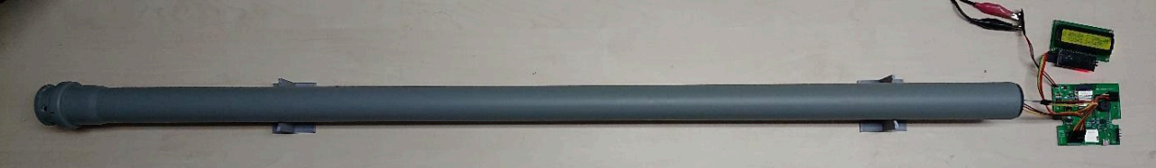
- a fully assembled MAG-BOARD
- connected sensors and LCD display
The V-block allows the gradiometer to rotate smoothly without changing its position.
Environment Requirements
Calibration must be performed in a magnetically clean environment. Avoid locations near electrical wiring, transformers, speakers, iron structures, or magnetic tools. External magnetic sources will affect calibration accuracy.
Preparing the Calibration Setup
- Place the V-blocks horizontally on a level surface
- Align them in the east-west direction
- Place the gradiometer tube on the V-blocks
- Connect the sensors and LCD display to the MAG-BOARD
- Power on the system
The display should show values for:
| Label | Description |
|---|---|
| U | Upper sensor reading |
| L | Lower sensor reading |
If the screen is blank, adjust the LCD contrast potentiometer on the board until the display becomes visible.
Step 1 — Sensor Alignment
Rotate the gradiometer tube slowly around its axis and observe the U and L values on the display.
Goal: Both U and L must increase and decrease simultaneously.
If they do not change together, adjust the sensor cap orientation until they respond the same way.
Step 2 — Zero Calibration
Press the NULL button on the electronics module (or use the Android app if connected).
The display will now show:
| Label | Description |
|---|---|
| D | Gradient value (difference between the two sensors) |
Step 3 — Fine Tuning
Rotate the gradiometer tube and observe the D value.
When the highest D value appears:
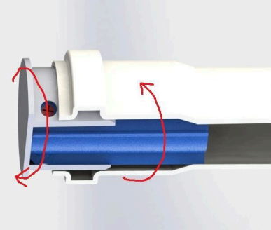
- Loosen the bottom adjustment screw
- Tighten the upper adjustment screw
If there is no bottom screw, loosen the two nearest screws instead. Always keep the screws slightly tightened during adjustment.
Repeat this process while rotating the tube.
Step 4 — Minimize Gradient Variation
Continue repeating the fine-tuning process until the change in D during one full rotation is minimized.
If the D variation cannot be reduced below approximately 1000, rotate the sensor cap slightly and repeat the tuning process.
Calibration can be time-consuming but is necessary for accurate measurements.
Securing the Calibration
After successful calibration:
- Check if any screws protrude from the sensor cap
- If necessary, sand off the protruding parts
Do not cut the screws with a knife or saw — this may disturb the calibration.
Then:
- Apply hot glue over the screws
- Push the assembly fully into the tube
This locks the sensors in place and preserves the calibration.
Final Assembly
Once calibration is complete:
- Install the electronics housing onto the tube
- Attach the LCD holder to the housing
- Route the sensor cables through the housing opening
- Connect the LCD and sensors to the MAG-BOARD
Pay attention to the orientation of the cables during installation.
Calibration Complete
The gradiometer is now ready for operation. The instrument can detect magnetic anomalies and buried ferromagnetic objects by measuring the gradient between the two sensors.
For best results, periodically verify calibration if the instrument is disassembled or subjected to mechanical shock.