Mechanical Assembly
The mechanical assembly step builds the physical structure of the gradiometer, commonly referred to as MAGRA.
The structure holds the sensors at a fixed distance inside a tube and provides mounting points for the electronics enclosure.
The system is designed so that most structural parts can be 3D printed or built using common hardware materials.
Required Materials
To assemble the mechanical structure you will need:
- MAGRA kit parts (or 3D-printed components)
- Plastic pipe
- Pipe cap
- Screws and mounting hardware
Recommended pipe dimensions:
| Parameter | Value |
|---|---|
| Diameter | 35–36 mm |
| Length | ~1 meter |
The exact tube diameter may depend on locally available plumbing pipes.
Required Tools
- drilling machine
- drill bits (3 mm, 6.5 mm, 10 mm)
These holes are used for mounting brackets and routing cables.
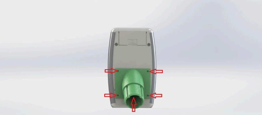
Attaching the Control Unit
The electronics housing containing the MAG-BOARD must be mounted to the gradiometer tube.
- Place the mounting bracket on the electronics housing
- Mark the screw positions on the housing
- Drill the mounting holes
- Attach the housing to the bracket using screws
Additional holes must be drilled for sensor cables (recommended diameter: ~10 mm).
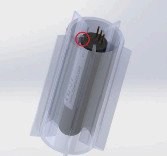
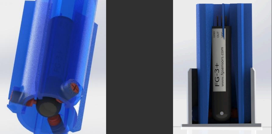
Preparing the Sensor Holder
The upper sensor holder is installed first.
- Insert the upper FG-3+ sensor into the holder
- Push the sensor until it passes the retaining latch
- Connect the sensor using the short sensor cable
- Secure the cable using hot glue
This prevents movement of the sensor during operation.
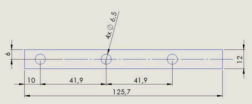
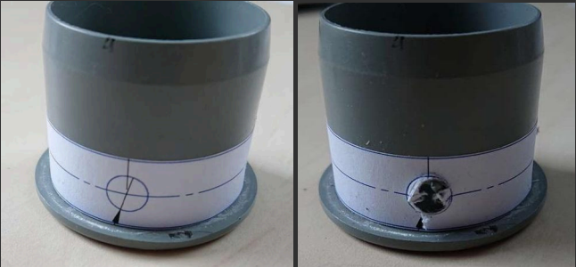
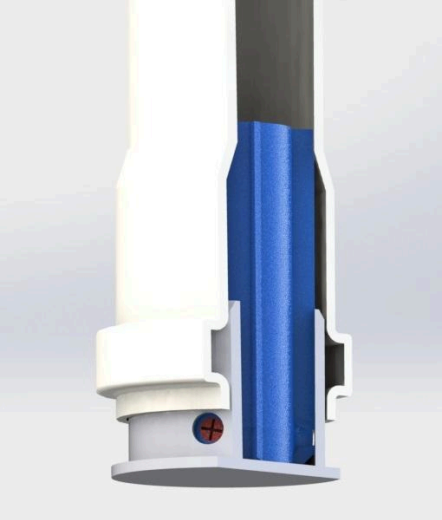
Preparing the Tube Cap
The pipe cap holds the upper sensor mounting system.
- Drill three holes in the cap
- Hole diameter: approximately 6.5–7 mm
These holes allow access to the screws used for adjusting the sensor alignment.
Installing the Sensor Assembly
Once the cap is prepared:
- Insert the sensor holder into the cap
- Insert the mounting screws through the drilled holes
- Tighten the screws until the sensor is centered
- Fix the bracket using hot glue
This assembly will hold the upper sensor in position.
Installing the Sensors in the Tube
- Connect the lower sensor using the longer cable
- Route the cable through the tube
- Insert the upper sensor assembly from the top
Recommended placement: upper sensor ~10 cm below the top of the tube. Secure the sensor using hot glue to prevent movement.
Sensor Orientation
Both sensors must be oriented in the same direction (both facing the same way). Incorrect orientation will result in incorrect gradient measurements.
Installing the Lower Sensor
- Lubricate the tube seal using soap or hand cream
- Insert the lower sensor assembly into the tube
- Adjust the sensor so that alignment screws remain accessible
Do not fully secure the lower sensor yet. The sensor position will be finalized during calibration.
Assembly Check
Before continuing, verify:
- sensors are installed in the tube
- both sensors are oriented the same way
- cables are routed correctly
- mounting bracket and electronics housing are secured
The gradiometer structure should now be ready for sensor installation and calibration.