Final Assembly
After completing sensor installation and calibration, the final step is assembling the electronics housing and connecting the remaining components.
This stage completes the mechanical construction of the gradiometer and prepares the instrument for operation.
Installing the Electronics Housing
The electronics housing contains the MAG-BOARD, display module, and user interface components.
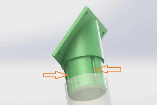
- Position the electronics housing on the mounting bracket attached to the tube
- Align the mounting holes
- Secure the housing using screws
Make sure the housing is firmly attached so that it does not move during operation.
Installing the LCD Holder
- Attach the LCD holder to the electronics housing
- Align the display with the viewing window
- Secure the holder with screws
The display should be clearly visible during operation.
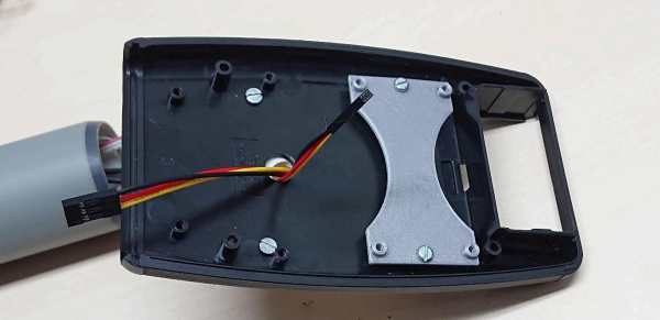
Routing Sensor Cables
- Pull the sensor cables through the housing opening
- Route the cables neatly inside the housing
- Avoid twisting or sharp bends
Proper cable routing helps prevent electrical interference and mechanical stress on the connectors.
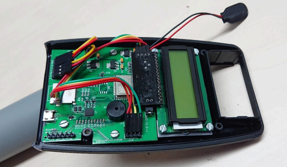
Connecting the Electronics
After routing the cables:
- Connect the sensor cables to the MAG-BOARD
- Connect the LCD display cable to the board
- Verify that all connectors are fully seated
Pay attention to cable orientation. Even if the cable colors differ, the start and end positions must match correctly. Incorrect orientation may prevent the system from operating correctly.
Securing Internal Components
Before closing the housing:
- check that all cables are connected
- verify that no wires are pinched
- ensure the MAG-BOARD is securely mounted
If necessary, use hot glue to secure cables and prevent movement during operation.
Final System Check
Before powering the gradiometer, verify the following:
- sensors are properly installed
- calibration screws are secured
- cables are correctly routed
- LCD display is connected
- electronics housing is mounted securely
Important Notice
Because the kit is assembled by the user, incorrect handling or assembly may damage components or cause malfunction. Due to the nature of DIY assembly, the manufacturer cannot guarantee correct operation if components are assembled improperly. However, online assembly support is available, and justified issues will be reviewed.
Gradiometer Ready for Use
Once the final assembly is complete, the gradiometer is ready for operation.
The instrument can now be used to detect magnetic anomalies and buried ferromagnetic objects by measuring the magnetic field gradient between the two sensors.